

1 PV DC combiner box structure and principle
Photovoltaic DC combiner box refers to a box that connects photovoltaic strings and is equipped with necessary protection devices to realize parallel connection between photovoltaic strings. Since the photovoltaic DC combiner box is arranged outdoors, the protection level is generally required to be above IP65.
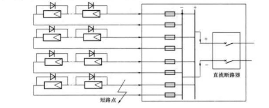
Figure 1 is a schematic diagram of a photovoltaic DC combiner box. Generally, fuses are used as protection devices on the input side of photovoltaic DC combiner boxes, and DC circuit breakers are used as protection devices on the output side, and lightning arresters are installed on the DC busbars.

2 Selection of fuses
For the selection of fuses, my country’s norms are not yet perfect. Referring to Article 690.35(B) of the National Electrical Code (NEC, 2011 edition), for the floating system (the photovoltaic DC collection system in my country generally adopts the floating method), the positive and negative poles of the string are installed with fuses. Because the short-circuit current of the photovoltaic DC combiner system is mainly provided by the photovoltaic modules, which is not as large as the AC system, the fuse of the photovoltaic DC combiner box should choose a photovoltaic special fuse that can adapt to this feature.
2.1 Short-circuit current
Assuming that the number of collecting channels of the photovoltaic DC combiner box is n, and the short-circuit current of each channel is Isc (Isc is the short-circuit current of the component under STC conditions), when the positive and negative poles of a certain string are short-circuited (see Figure 2), The short-circuit current flowing through the fuse of the string is (n-1)*1sc. For example, the number of PV DC combiner boxes is 24. When a string is short-circuited, the current flowing into the fuse of the string is 23Isc. .
2.2 Selection of fuses
The rated voltage of the fuse should generally not be lower than 1500V/1000V (IEC). The rated current of the fuse should generally not be less than 1.56Isc and not greater than the maximum rated current of the fuse allowed by the component manufacturer.
The reason for choosing 1.56Isc is according to the provisions of Article 690.8(A) of the “National Electrical Code” (NEC, 2011 edition). This regulation assumes that the maximum current of the module is 125% of Isc. The reason is that under certain cloud coverage conditions, the cloud is equivalent to a magnifying glass, and the light intensity can be 25% higher than the irradiance (1000W/m2) corresponding to the STC. The second is the National Electrical Code (NEC, 2011 edition) 690.8 (B), which requires that the fuse must be able to withstand 125% of the maximum current of the component. The end result is that the rated current of the circuit breaker is chosen as 125% of 125% of 1sc, which is 156% of 1sc.
3 Selection of DC circuit breakers
After several groups are connected in series and parallel, the DC circuit breaker is generally used as a protection device, and the output is passed through the DC circuit breaker. DC circuit breakers generally use 4P DC circuit breakers, and each two poles are connected in series as one pole to achieve a withstand voltage level of 1500V/1000V [at this stage, many manufacturers have successively introduced 3P DC circuit breakers, using 2 positive terminals in series to 2P+/1P - Mode output to reduce the volume of the shell frame and reduce the cost of equipment]. The rated current of the DC circuit breaker is also selected according to 1.56Isc.
4 The choice of lightning arrester
The output end of the photovoltaic DC combiner box should be equipped with a lightning protection device, and both the positive and negative poles should have lightning protection functions. Specifications should meet the following requirements:
1) The maximum continuous working voltage Uc:Uc>1.3Uoc(STC).
2) Maximum discharge current Imax: 1max(8/20)≥40kA, nominal discharge current In:I(8/20)≥20kA.
3) Voltage protection level Up, Up is the nominal discharge current I. The test values below, the specific application requirements are shown in Table 1.
4) The lightning arrester should have the function of disconnector and fault indication.
Two low-voltage lightning arresters can be used in series to improve the voltage level, but the sum of the protection levels of the two series-connected lightning arresters should be less than 4kV.
5 Monitoring device
In order to facilitate users to grasp the working conditions of photovoltaic strings in a timely and accurate manner and ensure that the solar photovoltaic power generation system exerts the maximum effect, the photovoltaic DC combiner box is generally equipped with a monitoring device. The monitoring device can monitor the current of each output circuit, the voltage of the DC busbar and the working state of the lightning arrester. The monitoring device generally recommends self-power supply to avoid the problem of large-scale and long-distance power supply. The monitoring device generally adopts the 485 communication method [bus serial interface communication, the maximum transmission rate of RS485 is 10Mbps, and the maximum transmission distance is 1500m. ); logic "0" is represented by the voltage difference between the two lines - (2~6V), the interface level is generally lower than the end of the chip to protect the circuit, and this level is compatible with TTL level, and can be connected with TTL circuit] , in order to prevent the overvoltage caused by lightning from the communication line from being introduced into the photovoltaic DC combiner box, it is required to install a signal lightning arrester at the 485 interface of the photovoltaic DC combiner box, and the communication line should be shielded by armor or laid through steel pipes. The way.

Post time: Aug-31-2022


